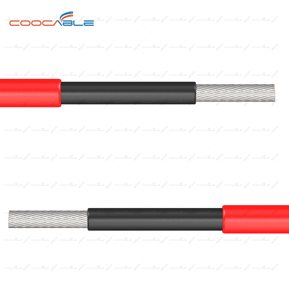
IEC 62930 solar cable
Interpretation of IEC Standards
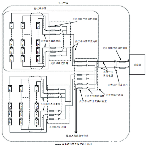
In a photovoltaic power station, the DC cable generally refers to the cable from the photovoltaic module to the photovoltaic array inverter, and the area involved is equivalent to the scope of the photovoltaic array. According to the schematic diagram of the photovoltaic array provided by IEC 62548:2016 (see Figure 1), the DC cables in the photovoltaic array usually include three sections of DC cables: the photovoltaic string DC cable, the photovoltaic sub-array DC cable and the photovoltaic array DC cable. . After multiple PV strings are connected in parallel, a confluence is performed at the PV string combiner box. In a confluence scenario, the PV sub-array DC cables and the PV array DC cables may not be involved; output from multiple string combiner boxes After the photovoltaic sub-array DC cables are connected in parallel, secondary confluence is performed at the photovoltaic array combiner box. In the secondary confluence scenario, the photovoltaic array DC cables may not be involved.
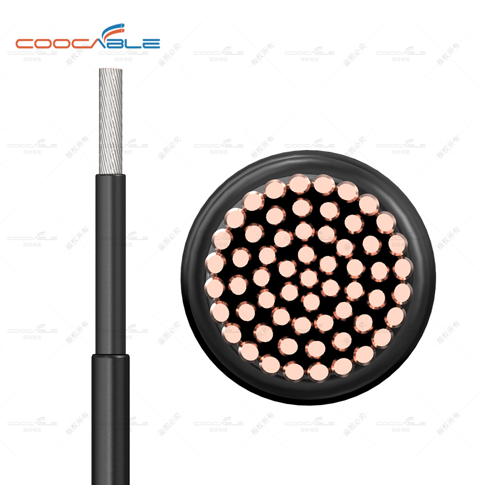
Suitable for cross-linked sheathed single-core cross-linked insulated power cables. These cables are used on the direct current (DC) side of photovoltaic systems and are rated for DC voltages up to and including 1.5 kV between conductors and between conductors and earth.
The difference with other standard solar cables
The IEC 62930 standard was published in 2017 and applies to the same range of cables as the EN standard.
IEC standard, it can be applied to a wider range, including options to choose class 2 conductors, extended sizes up to 400 square meters, multi-core, halogen-containing designs, higher storage temperatures and easier localization to international standards. The cables are designed to operate at the normal continuous maximum conductor temperature of 90 °C. The permissible use time at a maximum conductor temperature of 120 °C is limited to 20 000 hours.


