How to select cables for photovoltaic systems in a reasonable manner?
n recent years, the photovoltaic industry has witnessed rapid technological advancements, with individual solar modules achieving higher power outputs. Consequently, the current in series-connected modules has also increased, with high-power modules now exceeding 17A. In terms of system design, utilizing high-power modules and appropriate oversizing can reduce the initial investment and cost per unit of electricity. The cost of AC and DC cables in the system is significant. How can one design and select cables in order to minimize costs?
Selection of DC cables
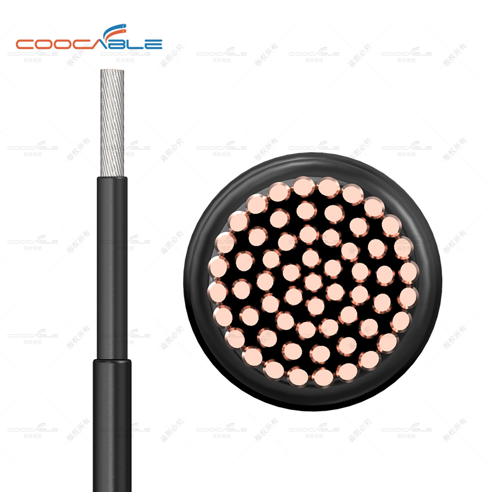
DC cables are typically installed outdoors. It is generally recommended to choose photovoltaic-specific cables that have undergone irradiation cross-linking. After being irradiated by high-energy electron beams, the molecular structure of the insulation layer material in the cable changes from linear to a three-dimensional network structure. The temperature resistance rating increases from 70°C for non-cross-linked cables to 90°C, 105°C, 125°C, 135°C, or even 150°C. This results in a 15-50% increase in the current carrying capacity compared to cables of the same specifications. These cables can withstand severe temperature changes and chemical corrosion, making them suitable for outdoor use for over 25 years. When selecting DC cables, it is important to choose products from reputable manufacturers with relevant certifications to ensure long-term outdoor use.
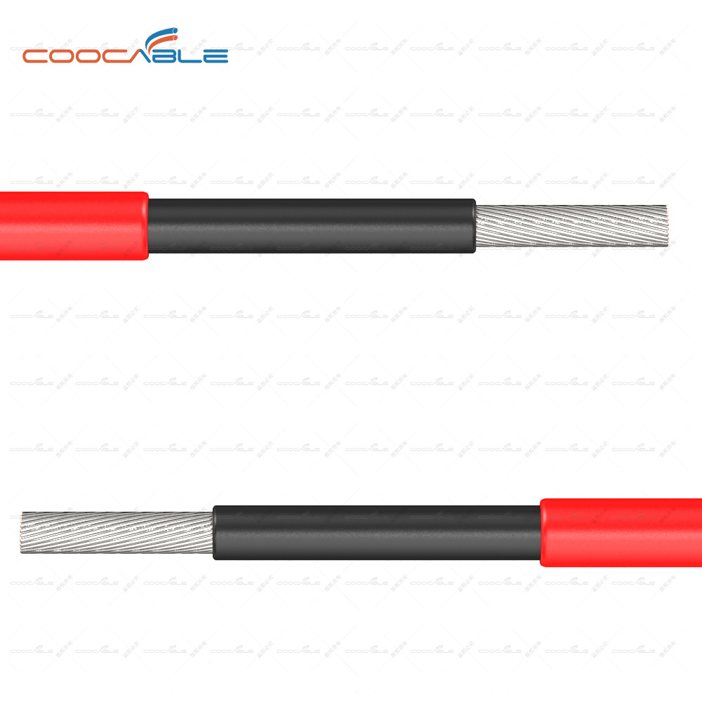
Currently, the most commonly used DC cable for photovoltaic applications is the PV1-F 1*4 with a cross-sectional area of 4 square millimeters. However, as the current of photovoltaic modules and the power of single inverters increase, the length of DC cables also increases, and the application of 6 square millimeter DC cables is becoming more common.
According to relevant standards, it is generally recommended that the loss of photovoltaic DC cables should not exceed 2%. We can use this standard to select and design DC cables. The line resistance of PV1-F 1*4mm2 DC cable is 4.6 mΩ/m, while the line resistance of PV 6mm2 DC cable is 3.1 mΩ/m. Assuming a working voltage of 600V for the DC module, a 2% voltage drop loss would be 12V. Assuming a module current of 13A, if a 4mm2 DC cable is used, the maximum recommended distance from the farthest module to the inverter should not exceed 120 meters (in series, excluding positive and negative poles). If the distance exceeds this limit, it is recommended to choose a 6mm2 DC cable. However, it is advisable to keep the maximum recommended distance from the farthest module to the inverter within 170 meters.
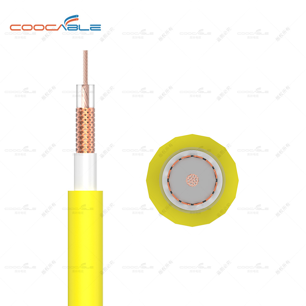
Selection of AC cables
To reduce system costs, photovoltaic power plants are now rarely configured with a 1:1 ratio of modules to inverters. Instead, the design includes a certain level of oversizing based on factors such as sunlight conditions and project requirements. For example, if 110 kW modules are used with a 100 kW inverter and a 1.1 oversizing factor is applied on the AC side of the inverter, the maximum AC output current would be approximately 158A. The selection of AC cables is determined based on the maximum output current of the inverter. Regardless of the degree of oversizing of the modules, the AC input current of the inverter will never exceed the maximum output current of the inverter.
Indeed, cables are crucial components in photovoltaic systems, and their cost proportion within the system is increasing. When designing a solar power plant, it is important to prioritize the reliable operation of the plant while striving to minimize system costs. Therefore, the design and selection of AC and DC cables in photovoltaic systems are particularly important.