Solar cable selection of photovoltaic power station
Cable selection in photovoltaic power station
1. Cable type
According to different application locations, cables in distributed photovoltaic systems can be divided into DC cables, AC cables and grounding cables:
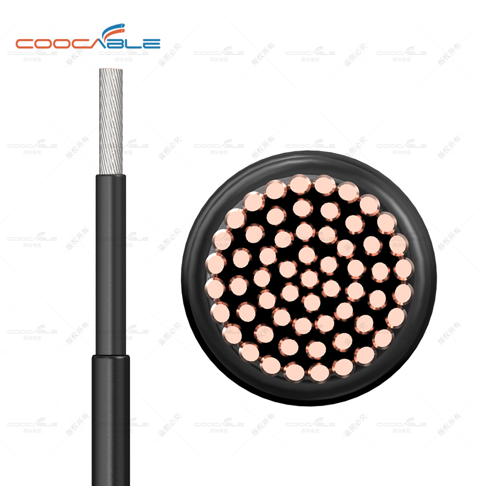
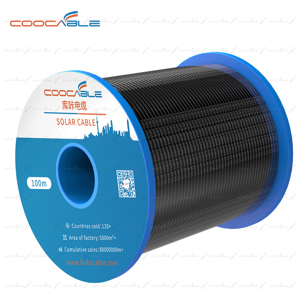
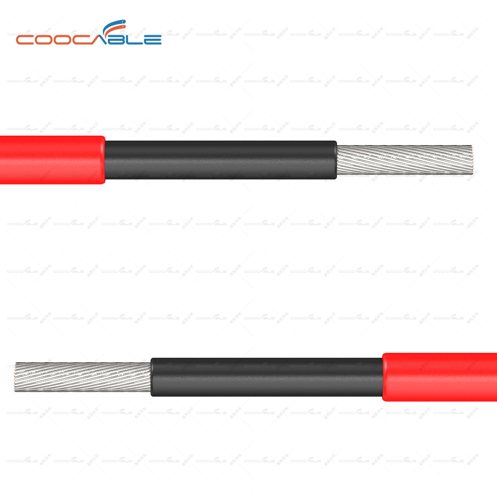
1. DC cables are mostly laid outdoors, requiring moisture-proof, sun-proof, cold-proof, ultraviolet-proof, etc. Therefore, the DC solar cables in distributed photovoltaic systems generally choose photovoltaic-certified special cables, considering the DC connectors and the output current of photovoltaic modules , the commonly used PV DC cable is PV1-F solar cable 1*4mm².
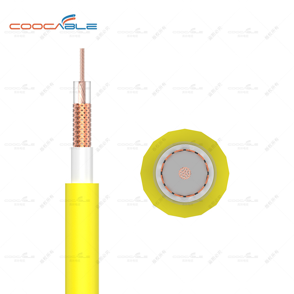
2 The AC cable is mainly used from the AC side of the inverter to the AC combiner box or the AC grid-connected cabinet. The AC cables installed outdoors need to consider moisture-proof, sun-proof, cold-proof, UV-proof, and long-distance laying. Generally, the YJV type is used. Cables; AC cables installed indoors need to be considered fire-proof, rodent-proof and ant-proof.
3 The grounding cable is mainly used for lightning protection grounding of components, component bracket grounding and inverter AC output grounding.") 2. Cable cross section
2. Cable cross section
At present, the selection of cable cross-section is mainly based on the relationship between cable diameter and current, and the influence of ambient temperature, voltage loss, and laying method on the current carrying capacity of the cable is often ignored. Here is a table of the current carrying capacity of the YJV three-core power cable commonly used, you can check the current carrying capacity of the cable in different use environments.
3. Voltage loss
The voltage loss in the photovoltaic system can be characterized as: voltage loss = passing current * cable length * voltage factor, it can be seen from the formula that the voltage loss is proportional to the length of the cable, so during field exploration, the array to The principle that the inverter, the inverter and the grid connection point should be as close as possible. In general applications, the DC line loss from the PV array to the inverter does not exceed 5% of the array output voltage, and the AC line loss from the inverter to the grid connection point does not exceed 2% of the inverter output voltage. In the process of engineering application, the empirical formula can be used: △U=(I*L*2)/(r*S).
Where △U: cable voltage drop -V
I : The cable needs to withstand the maximum current -A
L : length of cable laying - m
S : Cross-sectional area of the cable - mm²
r : Conductor conductivity-m/(Ω*mm²), r copper=57, r aluminum=34
4. Multiple multi-core cables are laid in bundles
In the actual application process, considering factors such as cable wiring methods and wiring restrictions, the cables of photovoltaic systems, especially AC cables, may have multiple multi-core cables laid in bundles, such as small-capacity three-phase systems. In the AC outlet, the 'one-line four-core' or 'one-line five-core' cable is used; in the large-capacity three-phase system, the AC outlet uses multiple cables in parallel instead of single-core large-diameter cables. In the case where multiple multi-core cables are laid in bundles, the actual current carrying capacity of the cables will be attenuated by a certain proportion. This attenuation situation needs to be considered at the beginning of the project design. This document provides a table to represent the correction in different situations. For the coefficient, please refer to "Appendix 2 Correction Coefficient for Bundled Laying of Multiple Multi-core Cables".
actual case
In a place with good light conditions, there is a village where the temperature in summer can reach 40°C. In order to seek welfare for the villagers, the village committee decided to install photovoltaic systems in the village, but the houses in the villagers' homes could not meet the requirements, so they could only be installed in the wasteland at the entrance of the village.
1 After measurement, 100 pieces of 255W modules can be laid in the wasteland, and one GW25K-DT inverter can be used;
The distance between the 2 modules and the inverter room is 30 meters, and the distance between the inverter and the village transformer is 50 meters;
3. The cables between the modules and the inverter, and the cables between the inverter and the grid connection point are all laid with copper wire exposed pipes;
4 The cable between the inverter and the grid connection point is a three-core cable.
The diameter of each cable needs to be confirmed.
Cable between module and inverter:
1 Cable type: 100 modules are divided into 5 strings, each string is 20; since the cables are laid in open pipes, and the lighting conditions on the project site are good, considering the moisture and sun protection, it is decided to use the photovoltaic special cable PV1-F 1*4mm²
2. Cable cross-section: single-core cable 4mm² current-carrying capacity is much larger than the short-circuit current of the component, which can meet the requirements;
3 Voltage loss:
△U=(I*L*2)/(r*S)≈(8*30*2)/(57*4)≈2.5V, the working voltage of the component is calculated as 200V, and the voltage loss is less than 200*5%= 10V, meeting the requirements;
Cables between the inverter and the grid connection point:
1 Cable type: YJV copper three-core AC cable;
2Cable cross-section: The maximum AC output current of GW25K-DT is 37A, the ambient temperature is 40 degrees, the open pipe is laid, and the 10mm² cables can meet the requirements after considering the allowance in the query table;
3 Voltage loss:
△U=(I*L*2)/(r*S)=(37*50*2)/(57*10)≈6.5V; the grid phase voltage is 220V, and the voltage loss is greater than 220*2%=4.4V, that's why GoodWe technical support department recommends 16mm² cables when recommending GW25K-DT AC cable configuration to customers.
The selection of photovoltaic cables not only conforms to the general power cable principles but also conforms to the characteristics of photovoltaic systems that require protection and a large temperature change range. A good selection of cables and laying methods can reduce the construction cost of photovoltaic systems and improve the photovoltaic system—the operational efficiency of the system and the stability of the system operation.